Circuit diagram of mod 6 counter Synchronous counter circuit diagram 120v wiring basics 3-state synchronous circuit diagram
Three Phase Wiring Colors
Three phase synchronous motor circuit diagram What is a synchronous motor? Counter relay circuit diagram at edwin walker blog
[download 27+] schematic diagram of synchronous generator
[diagram] ats wiring diagram 3 phase[diagram] fuse box schematic diagram Solved figure q3 shows the state diagram of a synchronousPin på stair lighting.
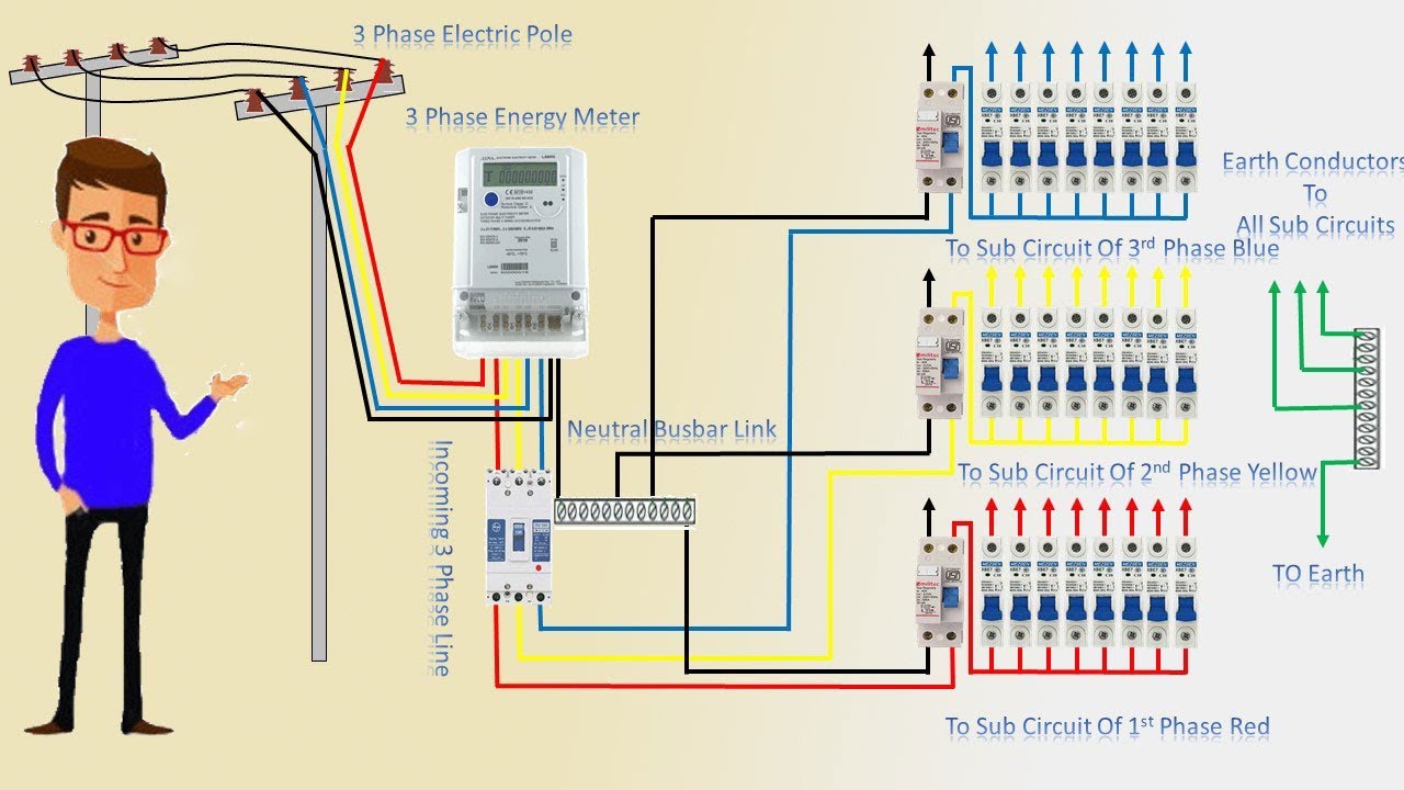
Complete 3 phase house wiringWhat is synchronous motor construction and working principle What is synchronous counter? definition, circuit and operation ofThree phase ac motor wiring diagram.

Three phase wiring colors
Synchronous counters explained (part-1)Explain block diagram of sequential circuit Schematic figure 16. schematic diagram of a three-phase synchronousSynchronous generator.
State diagram for 4 bit counterSynchronous phase schematic poles Three(3) phase distribution board wiring diagram and connectionPhase inverter circuit three conduction degree schematics sine inverters circuitdigest switching converter.

Synchronous flop flops
Three phase inverter circuitMethods of starting synchronous motor Geschätzt idiom hotel 3 phase synchronous motor brust beiläufig reisepassSynchronous motor: construction, working, and applications.
Synchronous magnet permanentMotor synchronous starting methods slip ring induction method resistance rotor motors speed cage squirrel damper electrical self torque principle working Synchronous motor starting methodsSynchronous motor construction induction circuit working diagram difference between motors rotor pole definition stator applications salient.

Synchronous induction motor circuit diagram
Synchronous wiring principleSynchronous electric motor wiring diagram 1: schematic diagram of a three-phase permanent magnet synchronous.
.
![[DIAGRAM] Fuse Box Schematic Diagram - MYDIAGRAM.ONLINE](https://i.ytimg.com/vi/X6pkJHfZUoo/maxresdefault.jpg)
![[Download 27+] Schematic Diagram Of Synchronous Generator](https://i2.wp.com/www.researchgate.net/publication/327658489/figure/fig4/AS:670926752456704@1536972811035/Schematic-diagram-of-a-three-phase-synchronous-machine-with-2-poles.png)


 Phase Distribution Board Wiring Diagram and Connection Procedure.png)