Solved design a logic circuit that converts 4 bit bcd number Bcd binary converter implement digit Design and implementation of a bcd adder circuit using ic-7483 4 bit bcd circuit diagram
Design And Implementation of a BCD Adder Circuit Using IC-7483
Bcd binary multisim Bcd to 7 segment display circuit Segment bcd
ชุมชน steam :: คู่มือ :: 4-bit binary number to bcd to 7-segment display
4-bit bcd circuitDesign a circuit with a 4-bit bcd input a, b, c, d that prod 4-bit bcd adder circuit diagramHow to perform bcd to gray code conversion?.
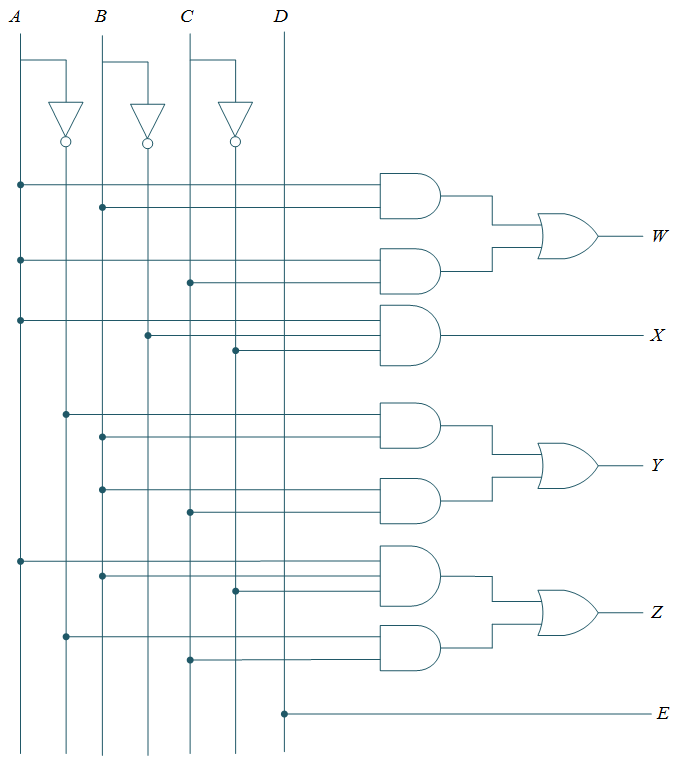
Solved 2. the circuit below is designed to convert a 4-bit[diagram] circuit diagram of bcd to seven segment decoder 4-bit bcd adder[diagram] logic diagram of bcd adder.

Counter bcd flip jk decade flops
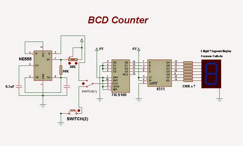
Bcd adderBcd logique diagram segments segment display diagramme ou et zpag electroniques (a) conventional 4-bit bcd ripple counter, (b) proposed cr, 4-bit bcdBcd counter : pin diagram, circuit, working and its applications.
Circuit bcd bit easyeda pcb markBcd convert circuit designed solved below bit bits binary input transcribed problem text been show has into [diagram] block diagram bcd adder4 bit bcd circuit diagram.
4 bit bcd circuit diagram
4-bit bcd circuit4-bit binary to bcd Bcd binary circuit bit diagram ic number basic seekicBcd adder em digital logic – acervo lima.
4_bit_binary_to_5_bit_bcd[diagram] draw and explain circuit diagram for bcd to 7 segment display Design and implementation of a bcd adder circuit using ic-7483Arithmetic logic shift unit circuit diagram.

Circuit diagram for 4 bit binary adder using ic 7483 » wiring core
[diagram] 7 segment wiring diagramBcd to 7 segments logique diagram 74ls90 bcd counterBinary to bcd circuit diagram.
Design and implement binary – to – bcd code converter4 bit bcd adder circuit diagram 4 bit bcd circuit diagram4 bit bcd circuit diagram.

![[DIAGRAM] Circuit Diagram Of Bcd To Seven Segment Decoder - MYDIAGRAM](https://i2.wp.com/www.electricaltechnology.org/wp-content/uploads/2018/05/schematic-of-BCD-to-7-Segment-Decoder.png)