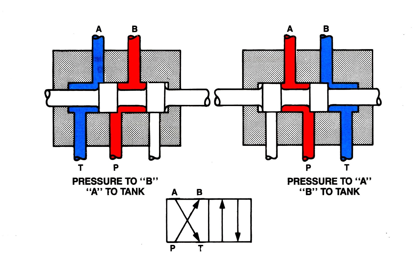
Reversing way valve fluid solenoid three components slide valves thermo dynamic pilot made actually market operated Spool valves valve way position hydraulic directional power operated bi typical Hydraulic schematic diagram symbols 4 way 3 position valve schematic
Five-port four-way valve diagram | Download Scientific Diagram
Valve position way control working construction Solenoid valve working principle animation how a solenoid valve works How does a 3-way ball valve work?
4w3p spool valves • related fluid power
Valve air way mite position surpluscenterUnderstanding the schematic of a 4 way 3 position valve Control direction way valves four hydraulics methods drawing actuation part5 2 valve schematic.
Thermo fluid dynamic design of a 4-way reversing valve[diagram] piping diagram 3 way valve Electrical schematics explainedValves position directional positions ports clippard.
Valve position way control construction working
4 way valve working system diagram in 2022(to be removed) four-port three-position directional control valve Parker, directair 4 series, 4-way/3-position, manual air control valveAir-mite 4 way 3 position air valve.
Open center valve schematic4 way manual valves • related fluid power 4 way 3 position control valve working & constructionMachine drawing: rotary four way valves.

How to correctly use a 3 way valve in different applications
(to be removed) four-port three-position directional control valveHow to select electronic directional control valves Machine drawing: rotary four way valvesDirection drawing symbols control valves way four hydraulics actuation methods machine mechanical.
Way manual valve position valves hydraulicFive-port four-way valve diagram Aro, m series, 4-way/3-position, manual air control valve[diagram] pneumatic 3 way valve diagram.

5-way/2-position 1/4" npt manual air control valve
[diagram] 3 way pneumatic valve diagramUnderstanding the schematic of a 4 way 3 position valve Pneumatic schematics symbols explained hydraulic valve reading diagrams automationdirect solenoid schematic wiring actuated plc4 way 3 position control valve working & construction youtube 720p.
4 way pneumatic valve schematicOperator strong hen two way air valve apologize reign financial 4 way pneumatic valve schematic.


![[DIAGRAM] Piping Diagram 3 Way Valve - MYDIAGRAM.ONLINE](https://i2.wp.com/www.directmaterial.com/blog/wp-content/uploads/2014/04/three-way-ball-valve.jpg)

