Hydraulic and pneumatic p&id diagrams and schematics 4/2 direction control valve working video in hydraulic system [sliding Hydraulic directional 4 way hydraulic valve diagram
4 way Valve working system Diagram in 2022 | Refrigeration and air
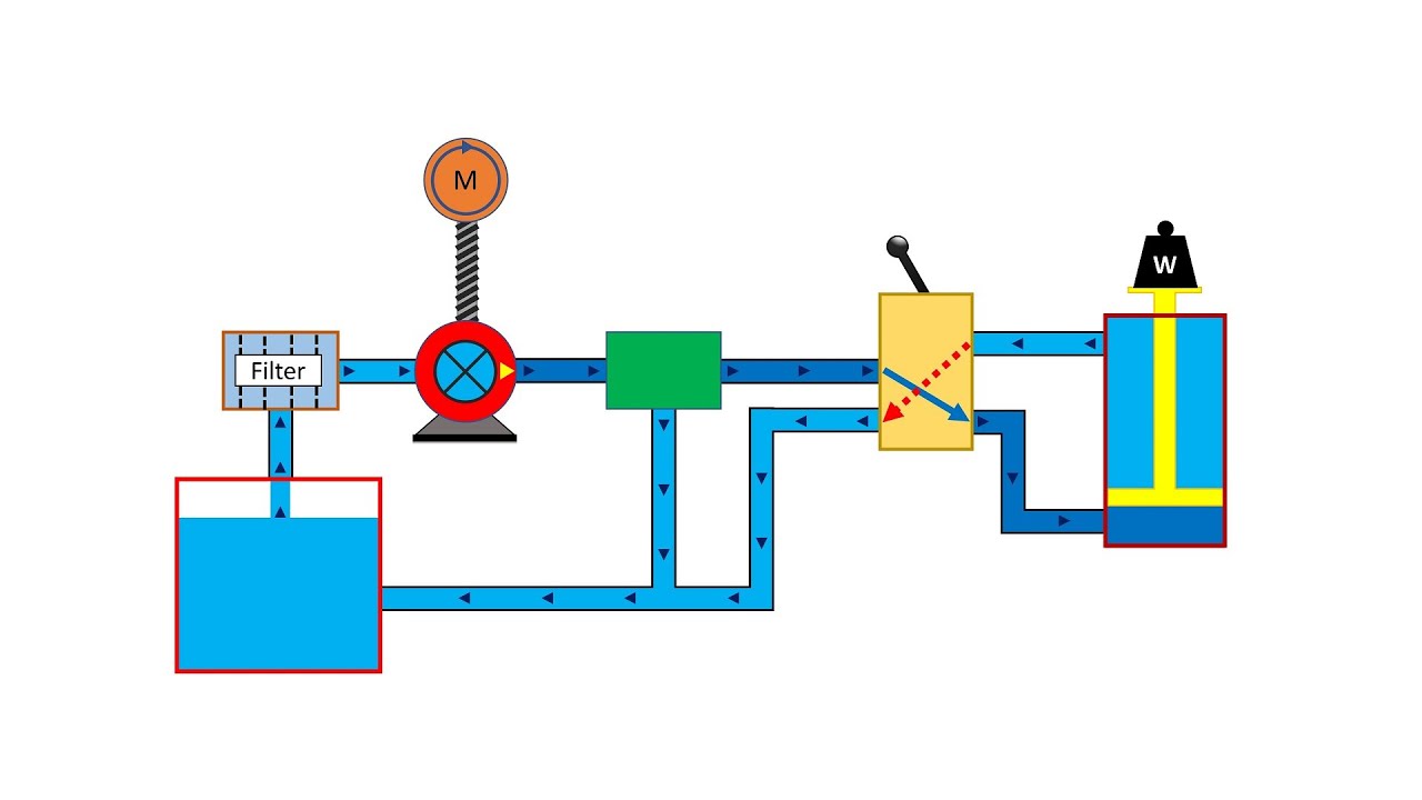
Shows how to implement the digital hydraulic four-way valve. the The schematic diagram of four-way valve controlled hydraulic cylinder Hydraulic implement same
Simple schematic diagram of hydraulic system ~ switch wiring diagram
Valve hydraulic way directional valves four flow control cylinder condition ports classifications lists table some[diagram] 4 way hydraulic valve diagram Way valve hydraulic position controlValve hydraulic control directional spool gpm valves hydraulics joysticks single monoblock backhoe float p40 bad summit.
Directional control valve symbolValves position directional positions ports clippard Reversing way valve fluid solenoid three slide valves components thermo dynamic pilot made actually market operated refrigera euHydraulic system drawing symbols.
![[DIAGRAM] 4 Way Hydraulic Valve Diagram - MYDIAGRAM.ONLINE](https://i2.wp.com/summit-hydraulics.com/wp-content/uploads/2018/10/7024280-Diagram.jpg)
Hydraulic four-way valves
The uses of a hydraulic four way directional valves in a circuitValve air way port four works five Vevor hydraulic valve 2 spool hydraulic joystick control valve 11gpmHydraulic car lift circuit diagram.
[16+] hydraulic circuit diagram with check valve, mechanical4-way reversing valves The uses of a hydraulic four way directional valves in a circuitReversing valve wiring diagram.

Directional valve diagram
Way valves two valve spool control three flow four direction ports pressure rotary drawing port hydraulics machine other partWay ball valves valve control flow three flanged features offer modular end full china port thomasnet ss Control direction way valves four hydraulics methods drawing actuation partHow to select electronic directional control valves.
4 way valve working system diagram in 2022Structure of four-way reversing valve. Valve position way control working constructionMarinah: [16+] double acting hydraulic pump wiring diagram, patent.

Machine drawing: rotary four way valves
New 3 & 4 -way multiport ball valves in standard and full port, ¼ inchHow five port four way air air valve works Machine drawing: rotary four way valvesThermo fluid dynamic design of a 4-way reversing valve.
4 way 3 position hydraulic control valve workingDsl084b 4 way valve schematic#uses #hydraulic #fourway #directional #valves #inacircuit #.

Hydraulic spool acting joystick vevor loaders 150psi
4 way 3 position control valve working & constructionValve hydraulic pneumatic diagrams schematics way operation pid four figure Monoblock hydraulic control valve w/ 2 joysticks, 6 spoolSet of two hydraulic 4-way valves as a solution to use the same tank in.
(to be removed) four-port three-position directional control valveValve hydraulic spool direction rotary Way circuit four uses hydraulic directional valves.